Caption
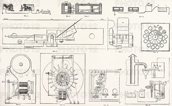
RAILWAY APPARATUS AT THE PARIS ELECTRICAL EXHIBITION: Fig. 1. Lartigue's Switch Controller. Fig. 2. Transverse Section. Fig. 3. Longitudinal Section. Fig. 4. Position of the Commutators during the Maneuver. Fig. 5. Pedal for Sending Warning to Railway Crossing, Elevation. Fig. 7. End View. Fig. 8. Electric Alarm. Fig. 12. Guggemos's Correspondence Apparatus, External View. Fig. 13. Interior of the same. Fig. 14. Annunciator Apparatus. Fig. 15. Controller for Water Tanks (Lartigue System), FRANCE, 1882
Date
1882
Credit line
Photo12/Liszt Collection/Quint Lox Limited
Reference
LZT13A36_327
License type
Rights managed
Available size
69.5Mb (3.5Mb) / 20.9in x 12.9in / 6263 x 3881 (300dpi)